Application scheme of non isolation LED fluorescent lamp based on LN2541
——18W constant current drive (24 string, 12 parallel)
1. brief introduction
This paper is a low cost non isolation LED fluorescent lamp application program based on LN2541 design.
LN2541 is a constant current control chip for driving LED. The system applies voltage range from 12VDC to 600VDC, and the duty cycle can be up to 100%. Support for AC 85V-265V input, mainly for non isolated LED drive systems. This scheme needs to drive 24 series of 12 parallel LED arrays with an input voltage range of 176VAC-265VAC.
this article includes circuit schematics, materials list, PCB diagram, performance test data and key components calculation methods.
Program basic characteristics:
- Very few peripheral devices
- Input voltage range: 176VAC-265VAC/50Hz
- System efficiency: 90%
- Power factor: 0.9
- The duty cycle is up to one hundred percent
- Analog dimming support
- Built in frequency jitter technology to reduce EMI interference
- Open circuit protection, short circuit protection, over temperature protection
2. Schematic diagram
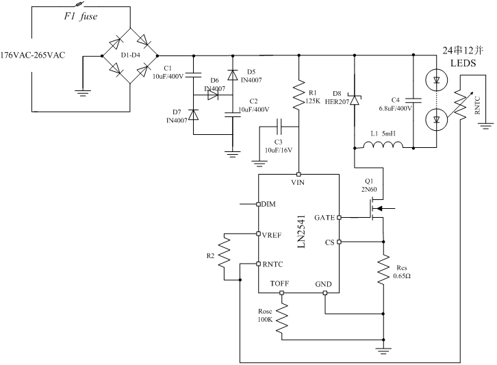
Note: the application input is 176VAC-265VAC, output 76V/240mA (24 string 12, and).
3. PCB drawings and prototype pictures

PCB diagram (single panel)

24 string 12 and prototype picture
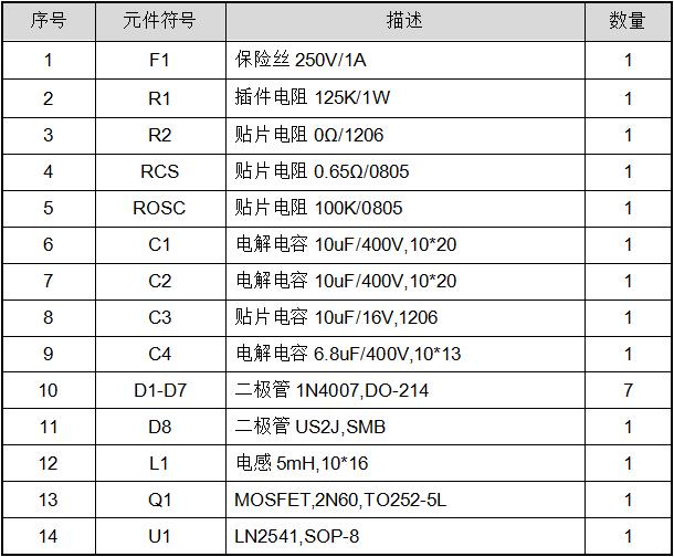
4.BOM
5. Test parameter
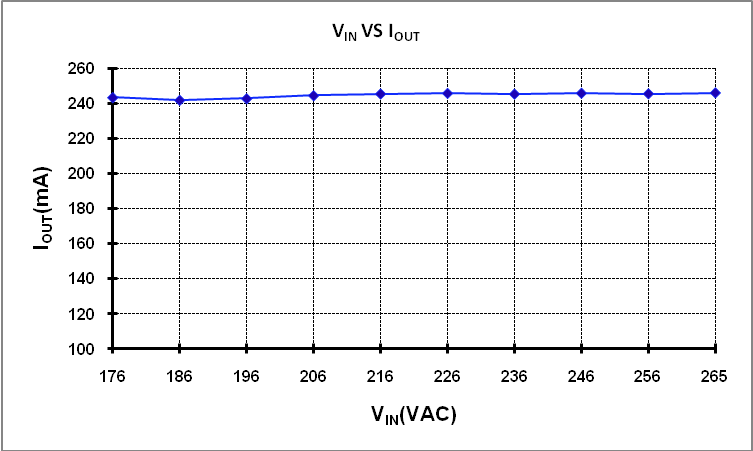
5.1 Linearity adjustment
The output current corresponding to different input AC voltages

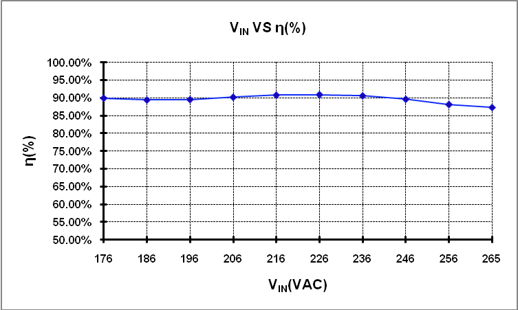
5.2 efficiency
The corresponding efficiency under different input AC voltages

5.3 power factor
The corresponding power factor at different input AC voltages

5.4 Correlation waveform
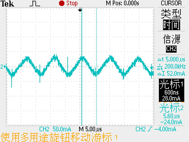
5.4.1 Measured Toff waveform Toff=5uS
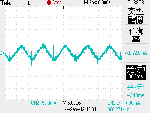
5.4.2 Output current ripple IRIPPLE=72mA
5.5.Dimming condition
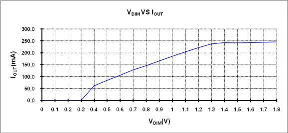
In DIM feet with a 100K adjustable resistor, you can achieve 0-100% dimming, curve as shown above.
6. Key component parameter design
Basic design parameters:

Note: the pressure drop of each LED is VF=3.2V, and the current is ILED=20mA.
Calculation of relative parameters
Output power: POUT= VOUT* IOUT=76.8V*240mA=18.4W
Peak current of inductance: IP=IOUT+IOUT*33%*0.5=[240+240*0.5/3]mA=280mA
Ripple current of inductance: IRIPPLE=2*(IP-IOUT)=2*(279.6mA-240mA)=80mA
Turn off time: TOFF=5uS
6.1.inductance
L= VOUT*TOFF/ IRIPPLE=76.8V*5uS/80mA=4.8mH,Take common specifications5mH。
Inductance line diameter: because IOUT is 240mA, so
Line diameter D=1.13* (1/J) ^1/2, in which J is current density, here take 6
, then D=1.13* (1/6) ^1/2=0.226mm, take 0.23mm.
here, select the 5mH inductor with a line diameter of 0.23mm.
6.2.TOFF set resistor ROSC
ROSC=TOFF/(4*10^-5)=5uS/(4*10^-5)=125K
Here is the resistance specification: 125K/0805/1%
6.3.Starting resistor R1
Because the IVIN is in the range of 1mA-20mA
Rmax= (VDCmin-10.5V) /1mA= (176*1.414-10.5) V/1mA=238K
Rmin= (VDCmax-10.5V) /20mA= (265*1.414-10.5) V/20mA=18K
and R1= (Rmax+, Rmin) /2= (238K+18K) /2=128K
PRmax=IINopmax2*R1=0.0012*128K= 0.128W
the values of 0.5W resistance 128K.
6.4.Sampling resistance
RCS=VREF/IP=0.2V/280mA=0.71
PRCS=0.22/0.71W=0.056W, so take 0.71 /0805/1% here
6.5.Switch tube
The switch withstand voltage needs more than the peak value of the input voltage,
is VDS> 1.414*VINmax=1.414*265V=374.71V, as far as possible to select the resistance RDSON small MOSFET
, here select 2N60, TO252-5L package.
6.6.Bypass diode
Its reverse voltage value VRMS> 1.414*VINmax=1.414*265V=374.71V, as far as possible to choose fast recovery time, small diode pressure drop, here select HER207
Note: This program is a non isolated structure, the normal operation, the drive board and LED lights are charged. When installing, connect the driver to the LED light board before switching on. Please observe the live operating rules strictly to avoid electric shock!


 Wechat